Ultrasonic Open Channel Flow Meter
Schedule A Consultation Today
*We respect your confidentiality and all information is protected.
Send


Hydrology & hydraulics
Ultrasonic Open Channel Flow Meter
Ultrasonic open channel flowmeters calculate liquid level via acoustic reflection time difference, then compute flow using weir structure formulas..
Features
  • Description
  • Features
  • Technical Features
  • Downloads
  • FAQ
  • Inquiry

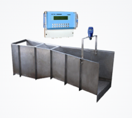
Product Introduction


Ultrasonic open channel flow meters calculate the distance from the sensor probe to the liquid surface by measuring the time of sound wave reflection after contacting the channel water surface and the speed of sound, thereby determining the liquid level. The channel flow rate is then calculated using formulas based on the structural dimensions of the weir.


Product Selection


1. Selection of Measurement Range and Accuracy

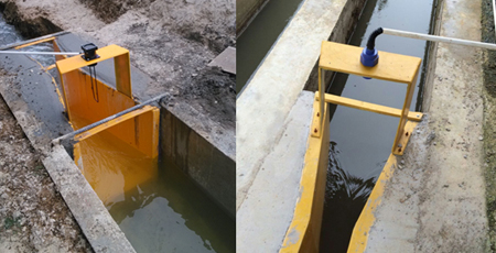
For agricultural irrigation terminal channels and sewage discharge channels, select a water level measurement range of 2-4m with a probe blind zone of 0.3-0.5m. 

Choose accuracy class based on actual needs for cost-effectiveness:For data statistics or process monitoring only (no precise control/measurement required): 

Select lower accuracy classes (e.g., 1.5, 2.5, or 4.0) for cost savings.For irrigation water charging or sewage discharge fee calculation: Choose higher accuracy classes (e.g., 1.0, 0.5, or above).

2. Selection and Installation of Weirs/Flumes

Three common types: triangular weir, rectangular weir, and Parshall flume.

Recommended for agricultural irrigation and sewage discharge: Parshall flume (calibrated via experiments for higher accuracy; 

requires unobstructed downstream flow with water level difference).Triangular/rectangular weirs: Based on theoretical calculations,

 prone to additional errors if usage conditions are ignored; require specific upstream-downstream elevation differences.

045fdfde-309b-4373-89b7-8f3e6f913c2a.png

3. Selection of Power Supply Type

Power supply types include 24V DC, 12V DC, 5V DC, 220V AC, etc. If there is a municipal power supply on-site, 

the 220V AC power supply type should be selected. If there is no municipal power supply on-site, priority should be given to 12V DC—since the supporting DTU/RTU all use 12V DC power supply, this ensures consistency of on-site power supply.

4. Selection of Signal Transmission Type

Digital signals (preferred): Support interfaces like RS485/RS232 and protocols such as HART, Modbus, Profibus. Resistant to environmental interference, 

stable transmission,easy to store/exchange, and compatible with data acquisition systems.Analog signals: Include 4-20mA DC current (commonly used), 

voltage, and resistance (rarely used).

5. Selection of Protection Class and Housing Material

Most of our solutions are applied in outdoor environments: the protection class of the probe part must reach IP68, the protection class of the instrument display part should not be lower than IP66, and the wire entry holes of the instrument must be sealed. The housing material should meet the requirements of non-oxidation, resistance to aging, and non-deformation within the range of ambient temperature and humidity. For applications in sewage discharge channels, it should comply with the Environmental Protection Industry Standard of the People's Republic of China HJ/T15-2007.

Installation of Ultrasonic Open Channel Flow Meter


●  Probe Installation Methods and Precautions

The ultrasonic open channel flow meter can be installed via bracket mounting or flange mounting. If on-site conditions permit, flange mounting is preferred—it is more convenient for adjusting the vertical alignment between the probe's sound emission direction and the water surface. Due to the existence of the ultrasonic flow meter's emission angle and blind zone, the distance from the highest water level to the bottom of the probe must be greater than the blind zone distance. When selecting the installation position, the probe should not be too close to the edge of the channel; instead, it should be installed above the centerline of the channel to avoid affecting the normal operation of the instrument.


image.png

                                                                             bracket installation                                    flange installation


Note: Regardless of the installation method, the incoming cables of the probe must be protected with a conduit; the emission surface of the probe must be exposed without any obstruction.


image.png


Technical data

  • Flow measurement range

    generally 0~40m³/s.

  • Flow measurement accuracy

    usually ≤±1%.

  • Liquid level measurement range

    common ones are 10cm~1m.

  • Liquid level resolution

    up to 0.1mm.

  • Liquid level measurement error

    generally less than or equal to 0.5mm.

  • Sensor range

    standard 1 meter, optional 2 meters

  • Operating environment temperature

    most products are -20℃~50℃.

  • Operating environment humidity

    ≤85%

  • Signal output modes

    common ones include 4~20mA current output, RS485, RS232, etc., and some products also support USB output.

  • Power supply

    AC power supply is generally 220V±10%, and there are also DC power supplies such as 12V, 24V, etc.

  • Protection level

    the instrument display part and the probe part are generally IP65, and some products can reach IP67 or higher.

Materials

Customer service will contact you within 24 hours!  
Read more
Message *
Name *
Enter your Name
Email *
Enter your Email
Submit

Related Products

Contact us now
No. 116 Pancheng New Street, Pukou District, Nanjing
© 2019 Welletronics Fluid Technology Pte. Ltd.
contact@welletronics.com +86 (0)25-86618785
No. 116 Pancheng New Street, Pukou District, Nanjing
Contact Us Now
Name
Your Phone